Dipping toes into ARM 32b programming with STM32 Nucleo
STM32
I grew up on Arduino, quite literally. Got my first Arduino Uno board when it was still in rev2, I had to change the AtMega IC a couple of times but I still have it and use it. However as my skills grew, the Arduino started to be the weak link. While it’s great to learn how to program embedded devices, communicate with stuff and for many applications, it is more than sufficient, I wanted to experiment with something more powerful. So, a logical step is one of many 32-bit ARM CPUs. Fortunately, there is a wide variety of development boards from ST Microelectronics, and together with their Cube IDE, programming them should be really easy. Should be.
I have never done any 32b ARM programming before. Yes, I have worked on Raspberry Pi, and on the Pico, which both are ARM based, but on both of them there are many abstraction layers and are actually overpowered. Also, learning low-level is always fun. So these are some of my first STM programs that I got to work, and some of my observations.
The board
I have won this board in a competition ran by ČVUT, I’ll spare you the details about it, but we have ended up at 2nd place and one of the prizes was this STM32 Nucleo-F030R8 board. It was still in it’s original box for almost a year before I have decided to try it - which is today.
Apparently the board is the go-to devboard, with Arduino-style (and compatible) headers for connecting compatible shields and integrated debugger/programmer, which is really cool. As the board’s name suggest, it has an STM32F030R8 MCU, which clocks tup to 48MHz, has 64KiB of FLASH memory, 8KiB of SRAM and a 32-bit Cortex M0 core. As for peripherals, 55 I/O pins that all can be mapped as external interrupts (woah), 12b ADC, builtin RTC, 11(!) timers, 2x I2C, 2x SPI, 6x UART (woah again) and an advanced PWM controller. As an AVR/Atmel fanboy, this chip absolutely slaps. So many things, can’t wait to try all of them. And cost of the standalone IC? Little around 3$. Insane.
So there is plenty of peripherals, the CPU is really freaking fast and what’s really neat is that all 55 I/O pins are 5V tolerant, meaning I don’t have to buy any level shifters or special 3.3V sensors. Yes, all STM32 chips run on 3.3V (except low powered ones that run on 1.8V).
Getting started
First of all, I have installed the entire STM32 toolchain - aka the one executable that takes 3 days to install, but contains everything. I have decided to go with STM32CubeIDE (great name btw), well because it was recommended on their page. Once that was installed, I had a bit of trouble with setting up the first project, but once I watched this great video, I was good to go. I have to say, when it all first launched I got overwhelmed extremely fast up to a point where I kind of wanted to exit it all, go back to my beloved VSCode and write C from scratch. So much boilerplate code. Personally I hate boilerplates, yes they might be useful but from a productivity standpoint, if you’re not 110% familiar with what’s in the boilerplate, you have to spend some amount of time analyzing it which decreases productivity and drive to do stuff. However in this case, all lines are commented and make enough sense, so it isn’t as bad as some JS frameworks.
The Programs
In this post I’ll be doing the basics, like blinking an LED, playing around with PWM, the ADC, interrupts and whatnot. I won’t be exploring communication protocols in this post - I’ll save that for later. So let’s go into it.
Blinky
Getting started with blinky, the “Hello World” of embedded programming - blinking an LED. This Nucleo board has an on-board LED on pin PA_5, and if you selected a board in the setup, it should already be configured as an output pin. That means that only thing that was left was to write accompanying code. Head over to the main.c, find the main program loop and.. what to write. Apparently there are two ways of interfacing with hardware on STM32 devices - LL and HAL. LL stands for Low-Level, and apparently is meant for advanced users. HAL stands for Hardware Abstraction Layer, which sounds cool but is essentially what Wiring is to an Arduino - just a bunch of functions to help you write more readable code (but I have to confess, seeing PORTA |= (0x02 << 2) & mask) makes some of my parts tingle). So a quick head over to this gigantic pdf for a reference, and we see that there is a HAL GPIO Generic Driver. Cool, bunch of interesting functions but one of them is HAL_GPIO_TogglePin(), which surprisingly toggles the pin given in params. That’s one part of blinky, the other part is the waiting. This was a little bit harder to figure out, since the whole HAL library is an abstraction, delay is sort of an abstraction of an abstraction. It uses some timers and internal interrupts, similar to Arduino’s delay function. This one is a bit more tricky under the hood, but I won’t be exploring that now.
So finally, the code looks underwhelming but performs as good as blinky can:
1 | int main(void) { |
As you can see, the blinky is done only in two lines. However the main.c file was over 250 lines long including comments. So much boilerplate code. In future snippets, I’ll be dropping anything that I did not wrote, for the sake of simplicity.
PWM Blinky
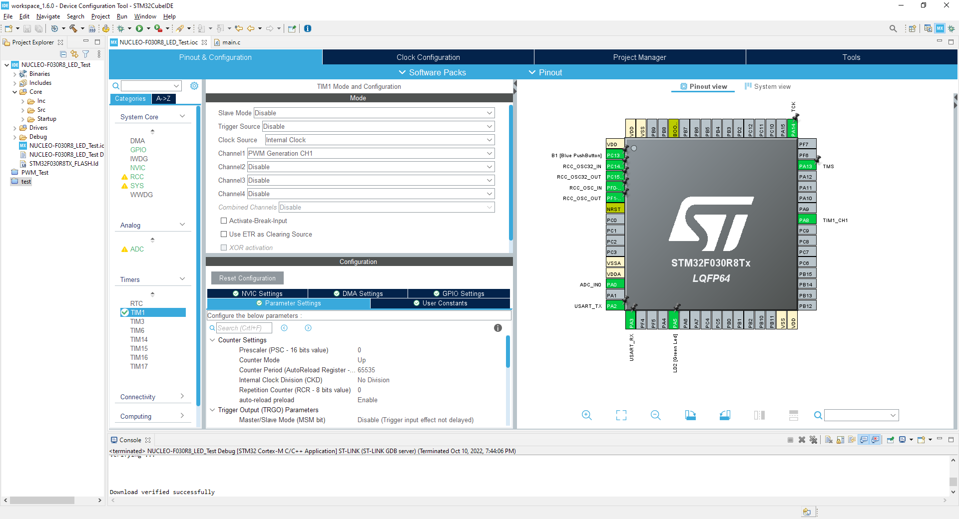
PWM is pretty simple concept that I hope you understand. If not, this article might help you. On Arduino, there is a very neat function called analogWrite(), which is a bit misleading since none AtMega MCUs on any Arudino have a DAC, but what gives. It creates a PWM signal on a supported pin. Under the hood, PWM has multiple modes that it can operate in. One of them uses one of the timers, that triggers an overflow on a set value which then changes the pin state. What’s cool on STM32 is that you can use one timer to control multiple PWM channels, each with different duty cycle (but same frequency and phase (in sync)). This is really cool if you for example control 3 of the same motors, where each requires the same frequency but might run at different speeds (duty cycle). Setting this up is a lot simpler and uses only one timer in contrast to 3 that would be needed on simpler platforms.
Anyways, after some digging around, I have found a way to interface the timer from within the code. First I had to understand a few internal registers like TIMx_ARR and TIMx_CCRx, they relation to frequency and duty cycle and some simple calculations for those parameters. Then it was a matter of setting one of available timers to output PWM on some channel (CH1 in this case), map it to a pin and write code. The code is really simple, we sweep from 0 to the size of CCR (65535 in this case), increasing the value by some amount in each step and writing that to the CCR. The MCU then outputs the value on pin, and we wait for 1ms. This makes the LED brighten up. Once we reach the maximum value, we begin to substract from the value, so LED would dim down. Easy enough.
1 | int main(void) { |
It is kind of interesting to read how the comparison and all other things work on the hardware level, like the different interrupts that are triggered, how often does the comparison take place etc., but that’s totally out of scope of this blogpost. If you’re interested, you can read more about it in your IC’s datasheet.
Dimming the LED with a pot
Very often I hear that people are scared by ADCs, again probably because of Arduino. There, its just a simple 10b ADC that you just read the value of, nothing else. In other systems, you will need to start the conversion manually, which sounds daunting but essentially what you do is just “ask“ the ADC for the value. When the conversion is done (because it takes some time, understand microseconds, or a few CPU cycles * sample rate), you can retrieve the value as a number and do whatever with it. In this example, we combine PWM output from the project before with ADC measurement, so we can sample value of a potentiometer connected to one of the pins and dim the LED appropriately.
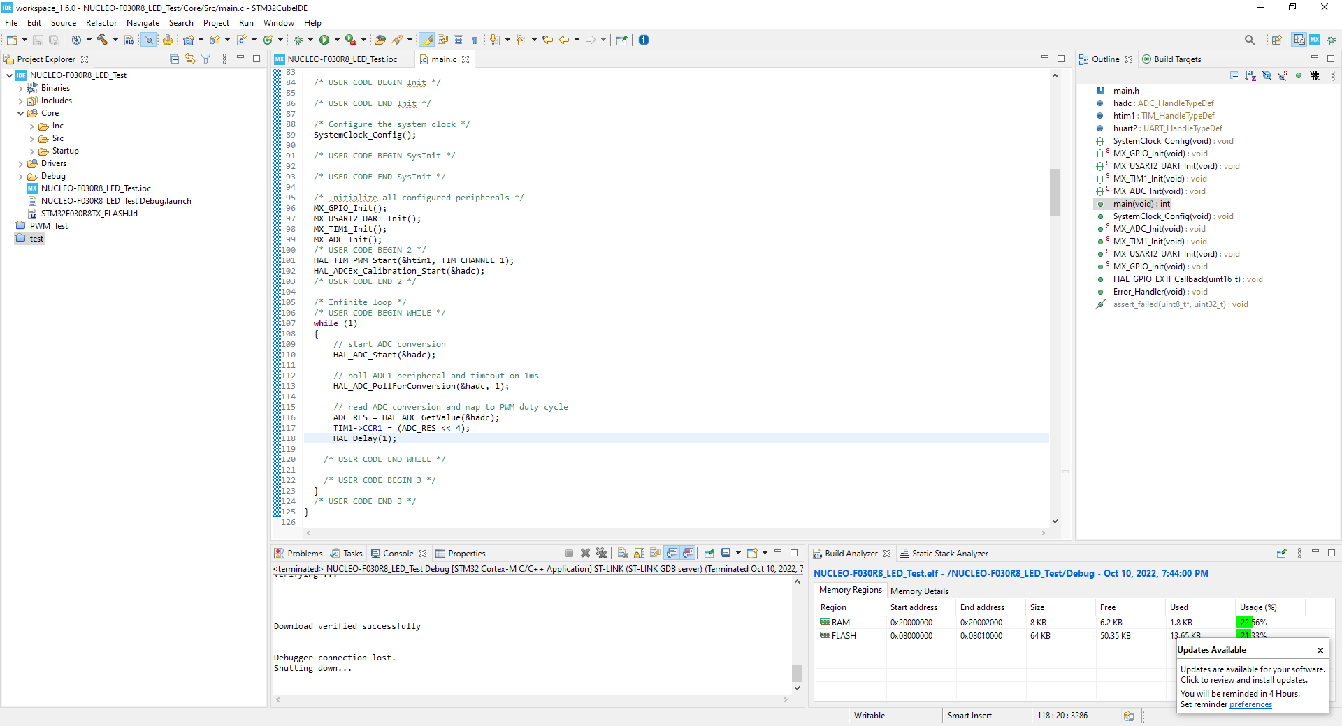
Code is again pretty simple, we set the ADC in the GUI to 12 bits, triggered by software and to do only one measurement per trigger. Next, we calibrate the ADC, and start the main loop. In the main loop, we start the conversion and poll for its completion. The STM32 has 3 different modes for ADC, and those are polling, interrupts and DMA. Polling essentially halts the entire CPU and waits for conversion to complete. If you have non-critical application and conversion is fast, you’d use this. If you want to do stuff correctly however, you’ll use interrupts. This allows CPU to continue computing during the ADC’s conversion process and after that’s done, it raises an interrupt which you’ll need to write a handler for. DMA mode transfers the result of measurement directly to the memory (DMA stands for Direct Memory Access) without CPU ever interfering with it. This is really cool if you’re doing multiple fast measurements at once. I have decided for polling method since the only thing I’m doing is dimming an LED. Once the conversion is done, CPU continues in the program, and retrieves the value of ADC into a variable. That value is then inserted into CCR of the timer’s PWM, but with a 4 bit offset. Simply so we can turn the LED bright, because timer is 16b and ADC is 12b, there are lowest 4 bits unused and they correspond to very small brigthness values, so we can just ignore them and start from the 5th bit. Really cool and easy.
1 | int main(void) { |
Interrupts
And the last project I want to do is to add an interrupt to the whole thing. As I’ve mentioned, there is an on-board LED as well as a button. So I want to hook the button up as a interrupt that when pressed, toggles the on-board LED. Program running normally would be the previous ADC+PWM project.
One cool difference from your basic Arduino is that all pins can be hardware interrupts. On Arduino Uno specifically, there are only 2 hardware interrupts. You can create software interrupts from any other pin, however hardware interrupts are much more robust. On STM32, enabling interrupt is a simple matter of toggling the checkbox in the pin’s configuration. Then, we just need to write an interrupt handler, or in STM32 terms a callback function, which processes our interrupt. Essentially, this function contains, what will happen after an interrupt is raised. This function should be as small as possible, containing least possible amount of blocking code, because when interrupt occurs, CPU completely stops whatever it is doing and proceeds to the IRQ handler. So if we need to do some complex operations, it is better to set a flag and then process that flag in the main loop.
1 | void HAL_GPIO_EXTI_Callback(uint16_t GPIO_Pin) { |
Noticed something about this snippet? We did not have to go to the main function at all. Just added this subroutine in the USER CODE 4 portion and done.
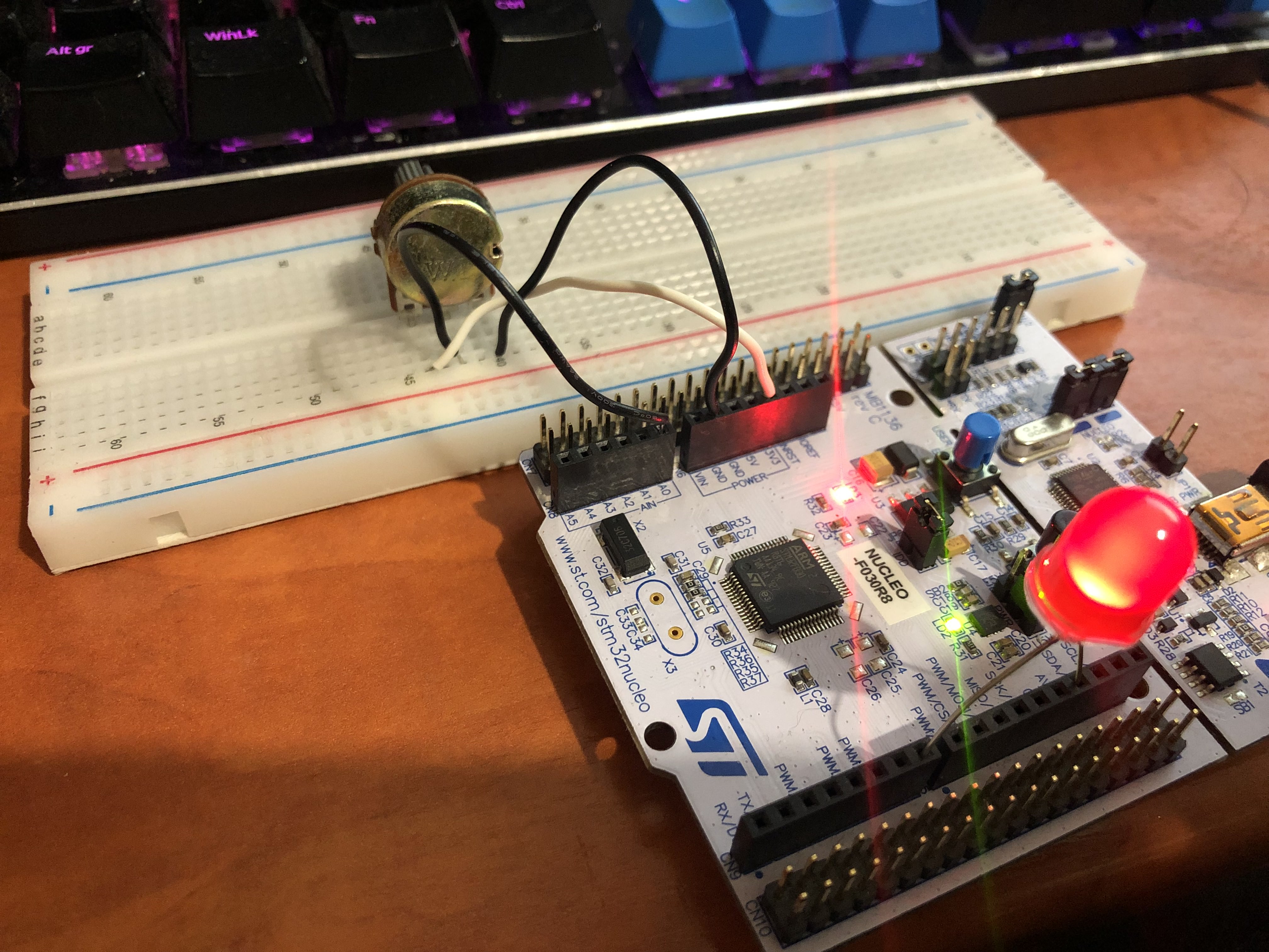
Here is a picture of the last project, LED is almost off and IRQ has been handled :)
Conclusion
Alas, we have arrived at the part I have been excited to write even before I started this journey (which took around 3 hours). Straight to the point I have to say, I have really enjoyed working with this board. Yes, there is a learning curve as with anything new, yes it is quite a bit different than Arduino or even RPico, and yes there are fewer “beginner’s” resources available. BUT, if you can navigate and read documentation and don’t mind tinkering around a bit, then I’d say this platform opens up so many possibilities. And I haven’t even explored the sh!t - communication with other modules.
From the start I was a bit skeptical, mostly because of the gigantic amount of boiler plate if gives you (contrary to the void main; void loop that Arduino makes), and even before writing a single line of code I was kind of cursing it, how unreadable the file would become and why is this necessary etc. After a few programs, yes the file is a bit messy but thanks to the outline pane you can navigate it pretty easily. And you can get to the user space parts really fast once you go through them a few times. Second thing I was skeptical about was about the configuration done via GUI and the rest via code. I am again used to low-level programming on Arduino (essentially ditching the Wiring language and sticking to the bare C), which requires you to set all registers and stuff either via macros, or by masking the register with appropriate bit masks. I can see myself getting confused and maybe even lost in a larger projects, where many peripherals are needed and configurations are at different positions, but I guess it’s just a thing of “getting used to it”. So fat I hadn’t had any major problem with that.
Another really, really awesome feature is the debugger. This board that I have has it on-board available via USB, as far as I understood it it is an ST-Link emulator thing used to program an debug in real-time, on the MCU itself. Which is amazing, no emulators, you can set breakpoint in the IDE, run the code and it will stop and respond to hardware changes you do. You can set watches on variables, see into different registers and do many, many cool thing. I haven’t focused on this in this blogpost because it is a little bit of an advanced topic, but it definately is worth a mention, even at the end.
For the final paragraph, if you are an experienced AVR programmer and you seek something with a lot more punch and functionality, go for the STM32. Yes, it is somewhat different but the potential is huge, documentation great and surprisingly not that hard. I really look forward to hooking up sensors to this board, messing with UART and PC, and doing more complex stuff in general.